
I started playing a while ago with loop antenna modelling, stretching them to the point where I obtained rather thin rectangles as shown in the below image.

I started simulating rectangles having a 1:2 shape ratio and at this point the antenna tends to display an ideal complex impedance, with R near 50Ω and jX around 0Ω. I then gradually reduced the width and increased the height of the element, caring to maintain the loop’s perimeter (and resonance) constant until, after a few iterations, the base and top horizontal segments shrank to about 5% of a wavelength (about 50cm for a 10m loop). A few more meticulous adjustments followed to bring the antenna to resonance at 28.5 MHz. In this configuration and with the feed point located 3m agl I obtained near-peak performance, reaching 8.42 dBi at 22° elevation; the impedance is 2.8Ω and jX is near zero. These parameters should make it possible to use either a transformer or an LC network of some description to bring the impedance close to 50Ω for coaxial cable matching. The 3 dB attenuation angle around the horizon is 90° (+/-45°) on each side and the antenna is still capable of delivering about -6 dBi (similar to a 1/4 wave element at ground level) at +/- 80° from the two lobes’ maxima (on the horizontal plane). So this antenna seems to be quite versatile. It should be relatively easy to build and install even in very confined spaces or in a field.
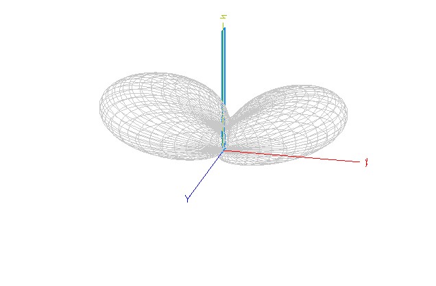
In summary: as you narrow the base and correspondingly increase the height of the loop, the gain goes up, the elevation goes down and the impedance falls. Going below 5% wavelength for the horizontal segments results in performance degradation.
After discussing with a few fellow amateurs who have experience with antenna modelling, the conclusion was that this loop essentially works like an array of two 1/2λ elements with the spacing between the two maximum current points set at about 1/2λ distance. This concept is similar to that of the Hentenna and the performance can be further improved by placing the feed point higher.
The advantages of stretching a loop to this point is that the antenna performs better than a dipole or a similarly sized end fed 1/2λ element and even a half square antenna. In fact, the performance is more aligned to that of a bi-square element but the width of the bidirectional beam is wider than that of a bi-square. In addition, the footprint of the antenna is much smaller and pretty much equivalent to that of a 1/2λ vertical.
The calculated dimensions for the base and top of this 10m loop are 0.5m and the sides measure 4.86m. The model can be scaled up or down and should be realistically easy to build and install from 14 MHz and above. Note that for 14 MHz the footprint of this antenna is just 1m.
